 English
 Arabic
How to Design 3D Print Models: The A-Z Guide from Zero to Hero (2025 Update)


Are you tired of failed prints and frustrated by designs that look great on screen but fall apart in reality? Or perhaps you're eager to bring your creative ideas to life but aren't sure where to begin with 3D modeling for 3D printing? You're in the right place.
Designing for 3D printing requires understanding how additive manufacturing works—the process of building objects layer by layer. This guide will equip you with the knowledge and skills to create models that not only print successfully but also look amazing and function as intended.
Understanding Design for Additive Manufacturing (DFAM)
Designing for 3D printing differs fundamentally from designing for other purposes like animation or visualization. In 3D printing, you must consider physical constraints and material properties from the outset.
Why DFAM Matters
When designing for 3D printing, you're creating something that will exist in the physical world, not just on a screen. This means:
- Physical limitations apply: Gravity, material strength, and layer adhesion all impact your design
- Support structures may be necessary for overhangs and bridges
- Material properties influence design decisions
Key Advantages of Design for Additive Manufacturing
- Complexity for free: Intricate internal structures cost no more to print than solid blocks
- Customization: Every print can be different without additional tooling costs
- Rapid prototyping: Test and iterate designs quickly
- Consolidation: Combine multiple parts into single prints
The DFAM Mindset
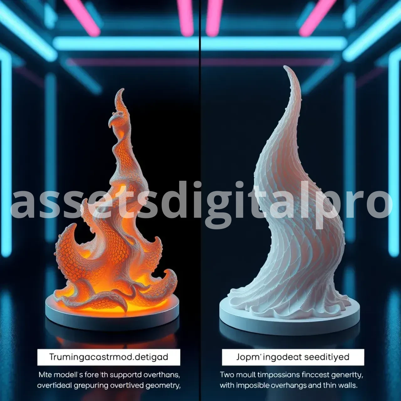
Successful 3D print designers think in layers from the start. This means visualizing how your model will be built up layer by layer and understanding how each layer needs to support the ones above it. Different printing technologies affect this approach:
- FDM (Fused Deposition Modeling): Consider layer lines, need for supports, and nozzle size
- Resin (SLA/DLP): Consider resin drainage, support removal, and orientation for detail preservation
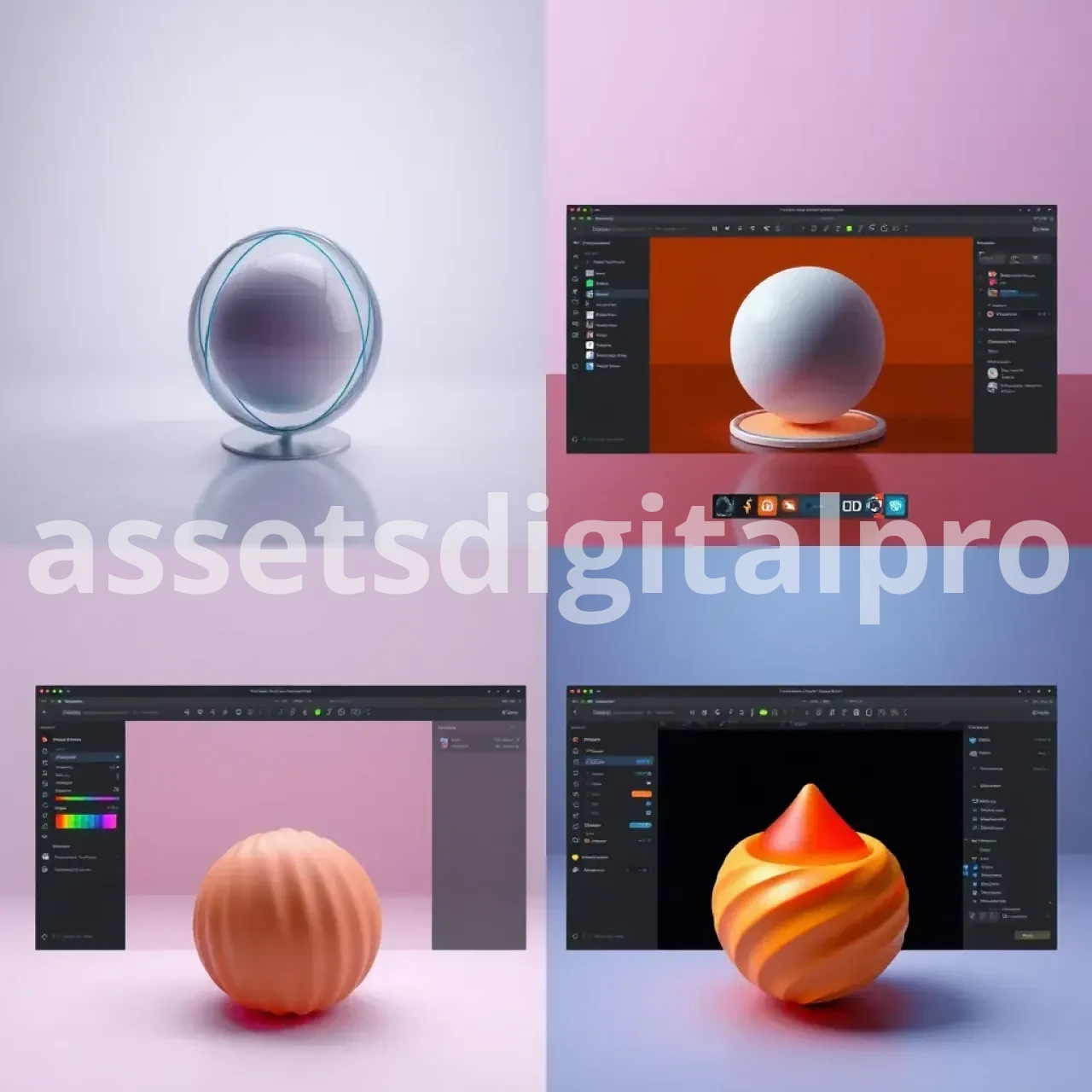
Choosing Your Digital Toolkit: Software for Designing 3D Print Models
The right software makes all the difference in your 3D modeling journey. Let's explore your options based on experience level and design needs.
Categories of 3D Modeling Software
Beginner-Friendly Options
- Tinkercad: Browser-based, intuitive interface, perfect for beginners
- SelfCAD: Easy to learn yet powerful enough for more complex designs
Parametric CAD Software
- Fusion 360: Professional-grade with free tier for hobbyists
- Onshape: Cloud-based CAD with excellent collaboration features
- FreeCAD: Open-source alternative with advanced capabilities
Digital Sculpting Tools
- Blender: Free, open-source with powerful modeling and sculpting
- ZBrushCoreMini: Entry-level version of industry-standard ZBrush
Mesh Editors
- Meshmixer: Essential tool for fixing and modifying existing models
Deep Dive into Top Recommended Software
Fusion 360
- Best for: Precision mechanical parts, functional objects
- Pros: Parametric workflow, integrated simulation, CAM capabilities
- Cons: Steeper learning curve, subscription model (free for hobbyists)
- Learning curve: Moderate to steep
- Cost: Free for personal use (with limitations), paid subscriptions for commercial use
- Official Site & Tutorials
Blender
- Best for: Organic shapes, characters, artistic models
- Pros: Completely free, extremely versatile, powerful sculpting
- Cons: Interface can be overwhelming initially
- Learning curve: Steep
- Cost: Free and open-source
- Official Site & Tutorials
Tinkercad
- Best for: Simple models, learning basics, quick modifications
- Pros: Browser-based, no installation, intuitive for beginners
- Cons: Limited for complex designs
- Learning curve: Very shallow
- Cost: Free
- Official Site & Tutorials
FreeCAD
- Best for: Parametric technical designs, open-source workflow
- Pros: Free forever, powerful parametric capabilities
- Cons: Less polished UI, occasional stability issues
- Learning curve: Moderate to steep
- Cost: Free and open-source
- Official Site & Tutorials
Which Software Is Right for YOU?
- Complete beginners: Start with Tinkercad
- Technical/engineering focus: Fusion 360 or FreeCAD
- Artistic/organic designs: Blender or ZBrushCoreMini
- Need to edit existing files: Meshmixer
Core 3D Modeling Concepts Every Designer MUST Know
Understanding fundamental modeling concepts will make your design journey much smoother, regardless of which software you choose.
Sketching & Constraints (for CAD)
Sketches form the foundation of CAD modeling. Using constraints ensures your design stays predictable and adjustable.
Common Pitfall: Avoid under-constrained sketches that can unpredictably change when parameters are modified.
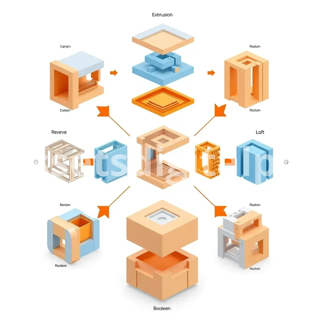
Extrusion, Revolves, Lofts, and Sweeps
These operations transform 2D profiles into 3D objects:
- Extrusion: Extends a 2D profile in a linear direction
- Revolve: Rotates a profile around an axis
- Loft: Creates a transition between different profiles
- Sweep: Moves a profile along a path
Common Pitfall: Complex lofts and sweeps may create unprintable geometry with too-thin walls.
Boolean Operations
Combining primitive shapes through:
- Union: Joins objects
- Subtract: Removes one shape from another
- Intersect: Keeps only the overlapping portions
Common Pitfall: Boolean operations can create non-manifold geometry if shapes barely touch or intersect in complex ways.
Working with Primitives & Sculpting Brushes
Building complex shapes from simple primitives (cubes, spheres, cylinders) is efficient. In sculpting software, brushes allow organic shaping.
Common Pitfall: Oversubdividing mesh before establishing basic forms leads to difficult-to-manage files.
Understanding Meshes
All 3D printable models ultimately become meshes consisting of:
- Vertices: Points in 3D space
- Edges: Lines connecting vertices
- Faces: Surfaces (usually triangles) defined by edges
- Normals: Vectors indicating which side of a face is "outside"
Common Pitfall: Inverted normals can confuse slicers, causing parts of your model to disappear.
The Golden Rules: Critical Design Principles for Printability
These principles will dramatically improve your success rate with 3D printing.
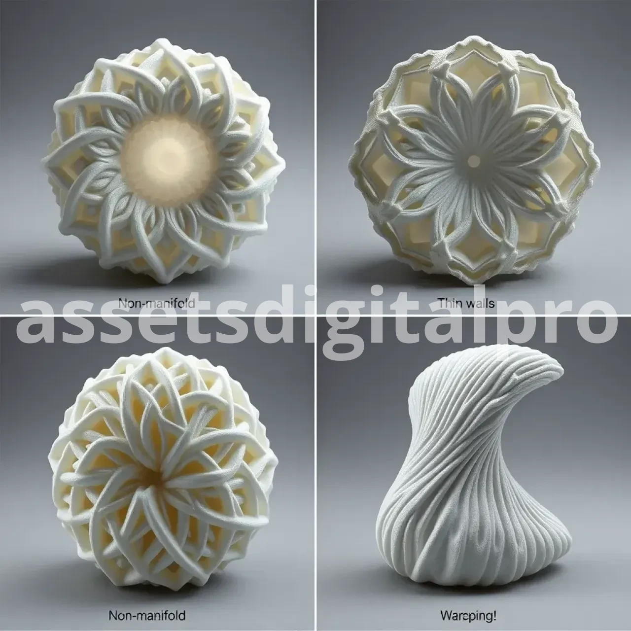
1. Watertight & Manifold Geometry
A printable model must be "watertight"—having no holes or gaps in its surface. Every edge must connect exactly two faces.
Tools to check:
- Meshmixer's Analysis tools
- Fusion 360's Mesh Validation
- Netfabb's Model Repair
2. Wall Thickness
Walls must be thick enough for your printer to create successfully:
- FDM printers: Minimum ~0.8mm (2× nozzle diameter)
- Resin printers: Minimum ~0.5mm for detail areas
Pro Tip: Design walls as multiples of your nozzle diameter for clean slicing.
3. Overhangs & Support Structures
The 45-degree rule suggests that angles steeper than 45° from vertical typically need supports. However, you can design to minimize supports:
- Use chamfers or gradual transitions instead of abrupt overhangs
- Split models along optimal seams for supportless printing
- Design sacrificial bridges that can be removed after printing
4. Bridging
Bridges are horizontal features spanning gaps without supports beneath:
- Most FDM printers handle 5-10mm bridges well
- Orient bridges parallel to the X or Y axis for best results
- Consider designing in your own temporary supports
5. Holes & Tolerances
3D printed holes typically print smaller than designed due to material expansion and printer limitations:
- Make horizontal holes teardrop-shaped for better printability
- For functional holes, add 0.1-0.3mm clearance depending on printer precision
- Design for press-fits with 0.1-0.2mm interference
6. Part Orientation on the Build Plate
How you orient your part affects:
- Strength: Layer lines create weakness in certain directions
- Surface finish: Top/bottom faces vs. side walls have different appearances
- Support needs: Minimize overhangs with smart orientation
7. Shrinkage & Warping
Different materials contract differently when cooling:
- ABS/ASA: Use rounded corners and avoid large flat areas
- Design built-in brims for high-warp materials
- Split very large parts to reduce warping forces
8. Infill & Shells
Design with internal structure in mind:
- Add internal ribs instead of solid infill for strength
- Create built-in reinforcement where needed
- Remember wall count affects strength more than infill percentage
9. Fillets & Chamfers
Rounded corners and edges improve:
- Strength: Reduces stress concentrations
- Printability: Gradual transitions print better
- Aesthetics: More professional appearance
10. Text & Fine Details
For legible text and crisp details:
- Embossed features: Minimum 0.6mm height/depth
- Debossed features: Minimum 0.8mm width
- Keep text above 5mm height for readability
11. Designing for Assembly
For multi-part prints:
- Allow 0.2-0.3mm clearance between moving parts
- Design snap-fits with flexible tabs
- Include captive nuts and bolt holes with appropriate tolerances
12. Material-Specific Considerations
Adapt designs based on material properties:
- Flexible materials (TPU): Need larger clearances, thicker walls
- Strong materials (Nylon, PC): Can have thinner walls, finer details
- Brittle materials (PLA): Need rounded corners to prevent cracking
Practical Workflow: Your First 3D Print Design Project
Let's design a practical phone stand in Tinkercad to demonstrate these principles in action.
Step 1: Plan Your Design
Start by sketching your idea and determining key dimensions:
- Phone width and thickness
- Viewing angle (65° works well)
- Base stability requirements
Step 2: Create the Base
- Add a box primitive (75mm × 50mm × 5mm)
- Round the corners using the corner tool (2mm radius)
- This provides stability and prevents tipping
Step 3: Add the Support Back
- Add another box (50mm × 40mm × 5mm)
- Position at 65° angle from base
- Ensure sufficient overlap with base (10mm minimum)
Step 4: Create Phone Slot
- Add a box primitive wider than your phone
- Make it slightly larger than your phone's thickness (+1mm clearance)
- Position at front of base and use as a subtraction tool
- Apply the Golden Rules: ensure walls remain at least 2mm thick
Step 5: Add Reinforcement
- Create triangular supports between base and back
- Apply fillets to all sharp corners (2mm minimum)
- This prevents stress concentrations and improves strength
Step 6: Final Checks
- Verify all walls exceed minimum thickness (2mm for FDM)
- Confirm there are no extreme overhangs requiring supports
- Check that the model is manifold using Tinkercad's inspection tools
Step 7: Export for Printing
- Export as STL with appropriate resolution
- Open in slicer software to verify printability
Beyond the Basics: Level Up Your 3D Print Design Skills
Once you've mastered the fundamentals, explore these advanced techniques:
Parametric Design
Parametric modeling lets you create designs driven by adjustable parameters:
- Define relationships between features
- Easily modify designs without starting over
- Create families of similar parts efficiently
Organic Sculpting
For characters, artistic pieces, and organic forms:
- Start with simple forms and progressively add detail
- Use symmetry tools to ensure balance
- Retopologize high-poly sculpts for printing
Non-Destructive Workflows
These approaches preserve editability:
- Use modifiers instead of direct edits
- Maintain construction history
- Group related features logically
Generative Design
Let AI help optimize your designs:
- Define constraints and goals
- Generate optimized structures
- Perfect for lightweight, strong parts
Exporting, Slicing & Pre-Print Sanity Checks
File Formats for 3D Printing
- STL: Most common, but stores only geometry
- 3MF: Modern format with colors, materials, and metadata
- OBJ: Good for colored/textured models
Export Settings
- Resolution: Higher for organic shapes, lower for mechanical parts
- Units: Ensure correct unit selection (mm is standard)
- Origin point: Place logically for print orientation
Slicer Preparation
Your slicer converts 3D models into printer instructions:
- Layer height: Affects detail and print time
- Support settings: Based on your design's overhangs
- Infill pattern and percentage: For strength and material usage
Pre-Flight Checklist
Before printing, verify:
- Model is manifold (watertight)
- No unintended thin walls
- Support generation looks reasonable
- Preview shows all features printing correctly
Troubleshooting Common 3D Print Design Flaws
Non-Manifold Geometry
- Symptom: Gaps or holes in prints, missing layers
- Fix: Use repair tools in Meshmixer or your slicer
- Prevention: Check for mesh integrity before export
Insufficient Wall Thickness
- Symptom: Fragile parts, holes in prints
- Fix: Thicken walls to minimum of 2× nozzle diameter
- Prevention: Use thickness analysis tools during design
Failed Overhangs
- Symptom: Drooping filament, poor surface quality
- Fix: Add supports or redesign to eliminate steep overhangs
- Prevention: Follow the 45° rule or design custom supports
Warping
- Symptom: Print corners lifting off build plate
- Fix: Add fillets to corners, use brims
- Prevention: Avoid large flat areas, split large prints
Your Journey Ahead
You now have the foundational knowledge to design successful 3D print models. Remember:
- Start simple and progressively tackle more complex designs
- Test and iterate—failed prints are learning opportunities
- Join communities to share experiences and get feedback
The best way to improve is through practice. With each design, you'll develop better intuition for what works in 3D printing.
Frequently Asked Questions
Is it hard to design 3D models for printing?
Starting with simple designs is easy, especially using beginner-friendly software like Tinkercad. As with any skill, complexity increases with ambition, but the learning curve is manageable with patience.
What's the easiest software to learn for 3D print design?
Tinkercad is the most accessible for absolute beginners, with its simple interface and primitive-based approach. For slightly more capability without much additional complexity, try SelfCAD.
How do I make my 3D model watertight?
Most CAD software naturally creates watertight models. For mesh-based designs, use tools like Meshmixer's "Analysis → Inspector" or Microsoft's 3D Builder automatic repair function.
Can I 3D model on an iPad for 3D printing?
Yes! Apps like Shapr3D, Nomad Sculpt, and uMake offer powerful 3D modeling on iPads, especially when paired with an Apple Pencil. Files can be exported as STL for printing.
How long does it take to learn 3D modeling for printing?
You can create simple designs within hours of starting. Basic proficiency takes about 2-4 weeks of regular practice. Mastery of advanced techniques can take months to years, depending on complexity.
Should I learn Blender or Fusion 360 for 3D printing?
It depends on what you want to design. Fusion 360 is better for precise mechanical parts, while Blender excels at organic and artistic models. Many designers eventually learn both.
How accurate are 3D printed parts compared to the digital model?
Consumer 3D printers typically achieve tolerances of ±0.1-0.5mm. Professional machines can be much more precise. Design with these tolerances in mind for functional parts.
Do I need to be good at art to design 3D models?
No! While artistic skills help for organic or aesthetic designs, technical 3D modeling relies more on spatial reasoning and understanding of geometry. Many successful designers have engineering backgrounds.
How do I design moving parts that work after printing?
Allow clearances of 0.2-0.3mm between moving parts, design with the printing orientation in mind, and consider adding break-away supports that can be removed after printing.
Can I edit existing 3D models I find online?
Yes, with mesh editing software like Meshmixer or Blender. However, parametric models (like Fusion 360 files) are much easier to modify than mesh-only STL files.
What's the difference between designing for FDM vs. resin printing?
Resin printers offer finer detail but require special attention to support structures and drainage. FDM designs need consideration for layer lines and bridging. Resin typically allows thinner walls and finer features.
How do I ensure my design is strong enough?
Orient your model so that layer lines don't align with stress directions, add fillets to corners, use appropriate wall thickness (minimum 1.2mm for structural parts), and consider infill patterns for internal strength.
Can I design threaded screws and bolts that actually work?
Yes, but design threads slightly larger than standard (0.1-0.2mm) and consider your printer's capabilities. For many applications, designing holes for standard metal hardware is more practical.
How do I fix a model that fails the manifold check?
Use repair tools in Meshmixer, Netfabb, or Microsoft 3D Builder. For persistent issues, recreate problematic areas or simplify complex geometry.
Should I design at actual size or scale later?
Always design at actual size with the correct units (usually millimeters). Scaling later can cause issues with tolerances and fit.


